Loading...

Sonik Speed Governer

Speed Governer for Road Safety

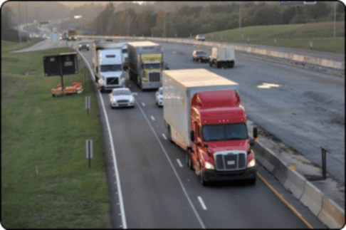
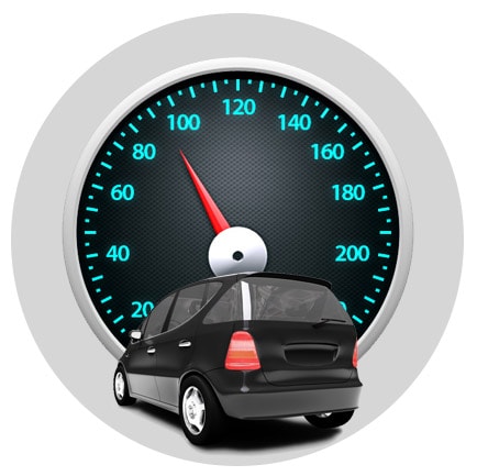
Speed management is a very important tool for improving road safety. however compliance with speed limits and reducing unsafe driving speeds are not easy tasks.

Our mission

To save valuable lives and our valuable environment while preserving our valuables resources thus adding value to our economy along with securing the interest of all stake holders.

Installation Guide:

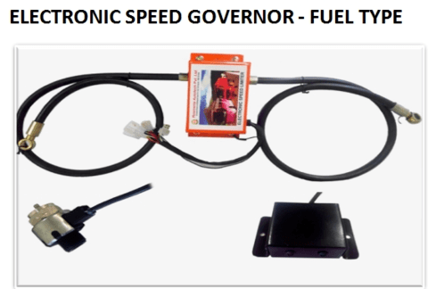
Important Note: Before installing ‘SONIK RSL’ confirm the vehicle voltage (12/24V) and use the
appropriate RSL(12/24V). The Speed Sensor type is also to be confirmed.

STEP:01
  • Find a suitable position to fix the E.C.U inside the cabin of the vehicle.
  • Connect the Power Supply Harness to the vehicle ignition system. Make sure that the red wire is connected to the positive supply & black should be grounded to the vehicle metallic body.
  • Connect the power supply to E.C.U & check whether the LED’s are working when the ignition key is in ‘ON’ condition & vice versa.
  • Now our E.C.U is ready to function.
  • STEP:02: Mounting of Fuel Control Unit
  • Find a suitable position to fix the F.C.U near the F.I.P/Engine & confirm whether the bypass screw of F.C.U can be adjusted. Before fixing the F.C.U make sure that the bypass screw is fully closed.
  • The connection of filter end & pump end should be decided as per the arrow marking in the name plate of the F.C.U. If it is connected reversely,the unit will not control the speed of the vehicle.
  • Provided banjo washer should be used for 14mm banjo bolt & step washer for 12mm banjo bolt.
  • First the filter end should be tightened properly with the help of suitable spanner.
  • Then the wire of the F.C.U should be routed safely towards the E.C.U & connect it in-order to check the functionality.
  • After connecting the F.C.U, purge the filter of the vehicle so that diesel will pass through our unit. This is done in order to check the functionality of our device as well as the removal of impurities/air if any.
  • Then the F.I.P/Engine side can be connected tightly with the help of suitable spanner.
  • Make sure that there is no air blocked inside the F.I.P, if yes purge the filter & remove all the air present.
  • Now our F.C.U is ready to function.
  • Only applicable for new generation vehicles which is equipped with electronic F.I.P
  • After examining the vehicle use appropriate straight end fittings (8/10/12mm).
  • The suitable fittings are to be fitted onto the F.C.U with the help of a spanner. Ensure proper usage of Teflon/Thread sealant on both the fittings in-order to avoid leakages.
  • Fix the fuel hoses to the fittings & tighten with the help of suitable hose clip.
  • Make sure to use max shorter hose at the outlet of the F.C.U (F.I.P/Engine side).
  • The connection of filter & F.I.P/Engine end must be as per the arrow marking in the name plate of F.C.U. If it is connected reversely, the unit will not control the speed of the vehicle.
  • First the filter end should be tightened properly with the help of hose clip.
  • Then the wire of the F.C.U should be routed safely towards the E.C.U & connect it in-order to check the functionality.
  • After connecting the F.C.U, purge the filter of the vehicle so that diesel will pass through our unit. This is done in order to check the functionality of our device as well as the removal of impurities/air if any.
  • Then the F.I.P/Engine side can be tightened properly with the help of hose clip.
  • Make sure that there is no air blocked inside the F.I.P, if yes purge the filter & remove all the air present.
  • Now our F.C.U is ready to function.
  • STEP:03: Mounting of Fuel Control Unit
  • Connect the sensor wire towards the E.C.U & rotate the sensor pin. Check whether the green LED (2nd from RS232 port) is blinking. This is done in order to confirm the functionality of the speed sensor.
  • Then mount the Speed Sensor to the gear box of the vehicle tightly. The speedometer end should also be fixed tightly.
  • Route the sensor wire safely towards the E.C.U
  • Now our Speed Sensor is ready to function.
  • Speed Sensor varies for different make of vehicles. So it can be confirmed by matching the sensor pin & the speedometer inner cable.
  • Only applicable for vehicles equipped with inbuilt electronic speed sensors
  • Connect the electronic sensor adaptor to the E.C.U.
  • Identify the pulse wire from the vehicle speed sensor using a multi-meter.
  • Mainly there will be 3 wires on the in-built speed sensor. Two of them will be fixed voltage values, (for example +5V & 0V) it depends on the vehicle make. One value will be varying as per the rotation of the wheel. This varying value can be identified as pulse wire.
  • Carefully tap the pulse wire & route it towards the E.C.U. 5. The pulse wire is carefully connected to the input wire (yellow) of the electronic sensor adaptor.
  • Now our Electronic Sensor Adaptor is ready to function.
  • STEP 04 – Programming the E.C.U
  • Connect the S.I.D (programmer) to the E.C.U. Make sure that our device is in ‘ON’ condition. ‘SONIK’ will be displayed on the screen.
  • Press the ‘SET’ button gently. Present speed/km will be displayed. If the device got hanged then please restart the system with the help of ignition key & continue the above steps again.
  • Speed can be adjusted by pressing the up/down buttons. Adjust the up/down button till the desired speed (as per govt. norms) is displayed.
  • After the desired speed is reached leave the button for a while so that ‘SONIK’ is again displayed on the screen.
  • Gently press the ‘DOWN’ button till the message ‘DATA SENT’ is displayed on the screen.
  • Now our ‘SONIK RSL’ is ready to function.
  • After taking the vehicle trial if the vehicle is not controlled at the set speed then adjust the ‘PPR’ using the programmer.
  • If the speed is overshooting then the ‘PPR’ should be decreased & vice versa.
  • Make sure that the overshooting is not due to bypass screw / reverse connection of Fuel Control Unit.
  • If jerk/white smoke is found during trial open the bypass screw up to an angle of 45o.
  • STEP:05: Adjust the ‘PPR’ only if required

    Note: PPR can be adjusted only when the vehicle exceeds/recedes the set speed more than 5kmph.
  • Connect the S.I.D (programmer) to the E.C.U & make sure that our device is in ‘ON’ condition. ‘SONIK’ will be displayed on the screen
  • Press the ‘SET’ button gently. If ‘SET’ button is pressed once present speed/km will be displayed. If ‘SET’ button is pressed twice ‘PPR’ will be displayed.
  • ‘PPR’ can be adjusted by pressing the up/down buttons. Adjust the up/down button till the desired “PPR’ is displayed.
  • After the desired ‘PPR’ is reached leave the button for a while so that ‘SONIK’ is again displayed on the screen.
  • Gently press the ‘DOWN’ button till the message ‘DATA SENT’ is displayed on the screen. Then S.I.D can be plugged out gently from the E.C.U.
  • Now the vehicle trial can be done.
  • STEP 06 – Adjusting the ‘Delay’ time
  • Connect the S.I.D (programmer) to the E.C.U & make sure that our device is in ‘ON’ condition. ‘SONIK’ will be displayed on the screen
  • Press the ‘SET’ button gently. If ‘SET’ button is pressed once present speed/km will be displayed.
  • If ‘SET’ button is pressed twice ‘PPR’ will be displayed.
  • R.S.L : Road Speed Limiter. E.C.U : Electronic Control Unit, F.C.U : Fuel Control Unit.S.I.D : Speed Input Device.F.I.P : Fuel Injection Pump. P.P.R : Pulse Per Revolution
  • Rating & Operating Conditions
    Parameter
    Min
    Max
    Units
    Supply Voltage(12v)
    Supply Voltage(24v)
    8
    21
    14
    27
    V
    Power Consumption 50(standby) 900(output) mA
    Operational Temp. -20 85 C
    Storage Temp -20 85 C
    Operational Humadity 0 100 %
    Electronic Speed Governer- Fuel Type
    Technical Spcification
    Operating Voltage 12V and 24V
    Operating Temp. Range -40 degree C to +80 degree C
    Solenoid Valve Current 0.6Amp
    Protection Class IP 57
    Protection Pass EMI/EMC
    Electric Protection Pass Reverse voltage, short circuit, Over Voltage
    Solenoid & ECU Housing Single Part
    Hose Pipe Gates, 100R1
    General Specification
    Electronic Control Unit
    Measurement (ECU) 85x75x35mm, 200gms
    Material-Enclosure ABS
    Protection Class IP65
    Signal Frequency 2Hz to 2kHz
    Fuel Control Unit
    Medium Diesel/Petrol
    Seal Material VITON
    Tempreature -10 - 150 C
    Portsize 1/4 BSP
    Orifice 3mm & 0.8mm
    Pressure 0-100PSI
    Coil DC 12/24V, 8.5W, IP65, 100% LED
    Sensor
    Type Hall Effect
    Voltage 8-30 VDC
    Pulse/Rev 8

    Support Help Line :
    +91 8824866866 (INDIA),
    +1-877-346-6006 (US/CANADA)
    Sales: +91 9829073554, 9660094554